
Chiller Capacity Control
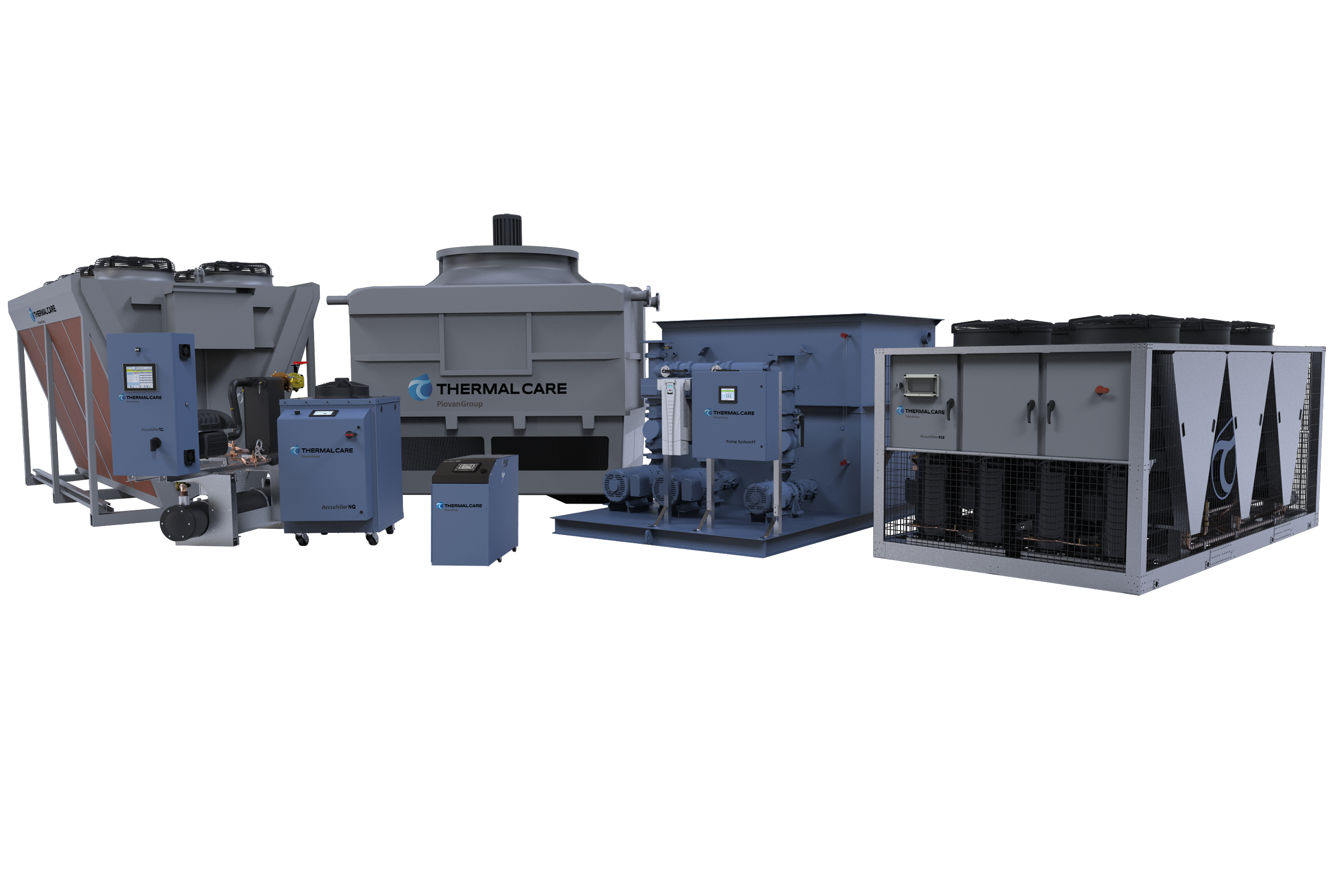
Chillers come in a variety of capacities and configurations. The following is a review of a specific aspect of chiller design known as capacity control. The type of capacity control used has a direct impact on a chiller’s operation as well as the technology incorporated into its design. This page will discuss the following:
- The basic concepts and terminology associated with chillers and their capacity ratings.
- Common scenarios that drive the type of control incorporated into a chiller’s design.
- Detail the various control designs available and their effects on operation and efficiency.
Understanding a Chiller 's Rated Capacity
The first concept to understand is a chiller’s rated capacity. Nominal conditions frame the ratings for chillers. These conditions detail the setpoint and condenser temperatures, and directly impact the chiller’s ability to reject heat from the system. Typically, for industrial process chillers, a nominal rating uses 50°F setpoint and 95°F ambient air for air-cooled chillers (or 85°F condenser water for water-cooled chillers). The rating uses “tons” as the unit of measurement. This is not the same “tons” associated with 2,000 lbs, but there is a connection. A cooling “ton” is based upon the amount of energy required to melt 2,000 lbs of ice, or 1 ton, in 24 hours. A cooling ton is equal to 12,000 Btu/hr. When a chiller is described as a 5 ton unit, it can provide 60,000 Btu/hr of heat rejection when supplying 50°F coolant in 95°F ambient air.
Load versus Capacity
Another concept to understand is load versus capacity. The load, often referred to as the heat load or cooling load, is the amount of energy the chiller is required to remove from the system. A chiller is installed to cool a process, such as an injection mold, which generates the heat. The chiller circulates the coolant to the process, transfers the heat from the process, and then delivers the now warmer coolant back to the chiller. The chiller removes the energy from the coolant and ultimately rejects it from the system. The chiller’s capacity must be greater than or equal to the process’s heat generation. If it is not, the chiller is only able to remove a portion of the energy, and the balance remains in the coolant. This will eventually lead to increased coolant temperatures because of an accumulation of energy in the system. Higher temperatures like this can affect how the process operates and also even shut it down completely. When this happens, the chiller is undersized. Conversely, there is an oversized chiller. This occurs when the chiller’s capacity is greater than the load. A scenario like this leads to the main topic of this article, capacity control.
If a chiller is oversized, to prevent the system from overcooling, capacity controls need to be included. Overcooling will drive the coolant temperature below the desired setpoint and will negatively affect a process’s ability to operate. The process will produce unsatisfactory product or even shutdown.

Chiller with multiple compressor design.
Compressor Cycling
The most basic method of capacity control is compressor cycling. The chiller’s compressor drives the refrigeration cycle, which provides the system with cooling. A compressor is either on or off and runs at 100% speed whenever it is on. Cycling the compressor stops the cooling in the chiller. It is a straightforward concept, if you do not need the cooling, turn it off. However, there are a few issues with this design. First, the on/off cycling can damage the compressor or reduce its life expectancy. For this reason, manufacturers require an anti-cycle delay that will only allow 12 starts per hour to protect the compressor. This means the compressor must wait at least 5 minutes from the time it last started before it can turn on again. As a result, the coolant’s temperature stability suffers. The oversized chiller will cool too much, triggering the compressor to cycle off. While the compressor is off, there is no energy removal from the coolant and the energy builds, increasing the temperature. With the anti-cycle timer active, the coolant temperature can continue to increase, eventually overshooting the setpoint until the timer is finally satisfied. This scenario creates a wave-like pattern of overcooling followed by overheating. This repeats until the load on the system changes.
Hot Gas Bypass
The next method of capacity control addresses the lack of temperature stability from compressor cycling. It is hot gas bypass (HGBP) and refers to a modification of the refrigeration circuit in the chiller. It does exactly as the name suggests - bypasses hot gas directly to the evaporator. This creates an additional heat load that prevents the chiller from overcooling and needing to turn the compressor off. HGBP avoids the compressor cycling issue and the resulting temperature instability. However, this solution wastes significant energy. For example, a 10 ton chiller with only a 5 ton load still operates like a 10 ton chiller and consumes the same amount of energy a 10 ton chiller normally would.

Hot gas bypass (HGBP) bypasses hot gas directly to the evaporator to prevent the chiller from overcooling.
Larger capacity chillers can use a combination of cycling and HGBP because multiple compressors are used to meet the full design capacity. This design provides stages of turning compressors off, or unloading. The more compressors, the more stages of unloading. With multiple stages, it improves the chiller’s ability to match the load with discrete steps. It avoids the large temperature swings and anti-cycle timers of a single compressor chiller. Additionally, with compressors off, it reduces overall energy consumption. On the last stage or compressor, HGBP ensures temperature stability while only wasting a fraction of the energy.

How HGBP is configured within the refrigeration cycle.
Digital Scroll Compressor
For chillers that are limited to one or two compressors, new technologies can actively adjust capacity while also saving energy. A digital scroll compressor operates in two states – the loaded state and unloaded state. In the loaded state, the compressor operates like a standard scroll at full capacity. In the unloaded state, there is no compression or no capacity. Controlling between these two states, loaded/unloaded, the compressor earns its “digital” name. By physically separating the scrolls in the compressor, it will move from loaded to unloaded and back. The amount of time spent in each of these two states modulates the capacity of the chiller. With no compression, the compressor consumes much less energy while remaining on. This avoids the cycling issues mentioned earlier.
Variable Speed Design
The leading technology for capacity control is a true variable speed design. The chiller’s controller constantly monitors the heat load. Using a variable speed drive, it adjusts the compressor speed for peak efficiency, temperature control, and eliminates the need for hot gas bypass. By automatically adjusting the speed, the chiller only works as hard as necessary to provide the optimum performance with significantly reduced energy consumption. Studies have shown that a 20% reduction in compressor speed can lead to a 51% energy savings. This solution encompasses the best performance and protections for the system available today.

Based upon your process’s cooling demand, and the overall variability of that demand, the right capacity control solution is available to match your needs.